IMAGS Technical Documentation
Sensors
IMAGS works by measuring and recording the conductivity of skin in real time. This is done by using a pair of sensors that send a small, non-harmful electrical current through the skin. We then measure how strong that current is at one sensor versus the other sensor, send it to the circuit, and process it to get the current GSR value. The circuit then connects to the IMAGS website via Bluetooth, where we can watch and record the live GSR values. Each component of the IMAGS device is simple enough to replicate at home. You will need Velcro straps, copper tape, solder, a soldering iron, solder paste, and a connecting cable.
The sensors used for IMAGS are simple yet robust enough to reliably send GSR data to the circuit. They are ring-like adjustable sensors that connect a copper patch to the underside of the pointer and middle fingers. While each pair of sensors may have slight variations in readings in comparison with other sensors, we account for this in the software by taking a baseline reading.
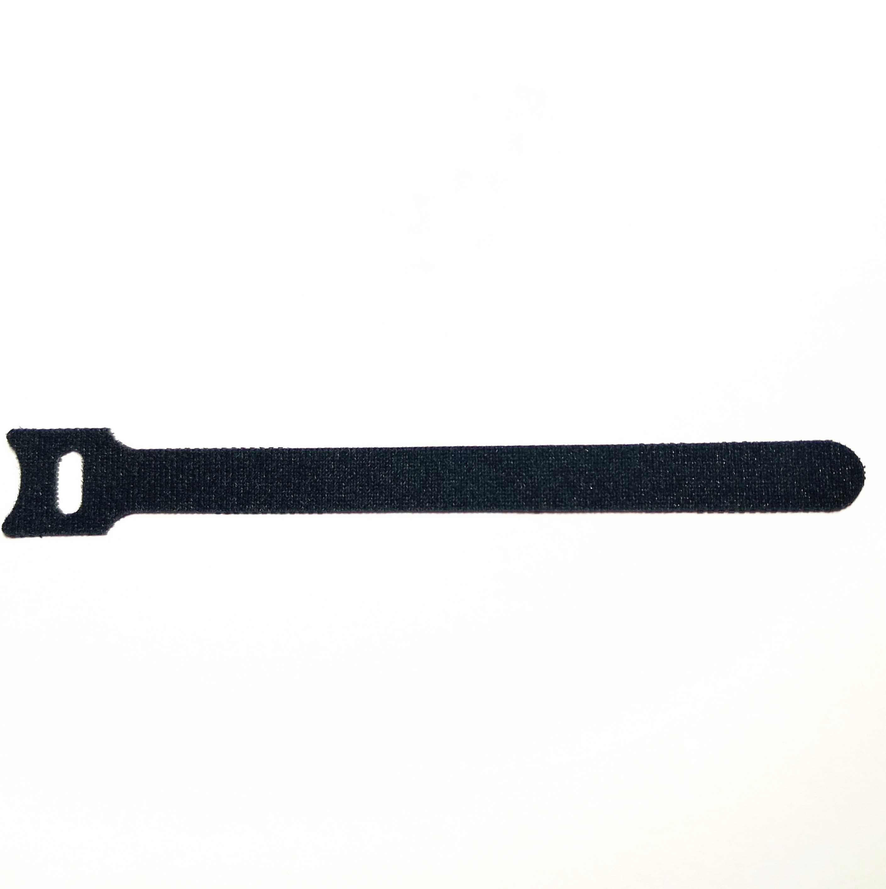
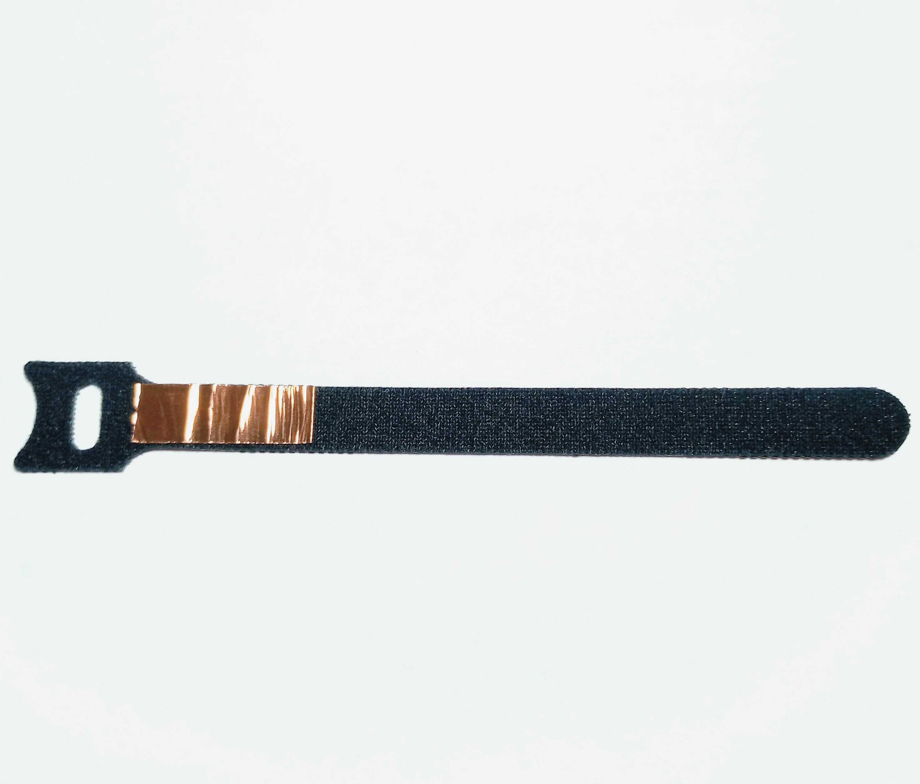
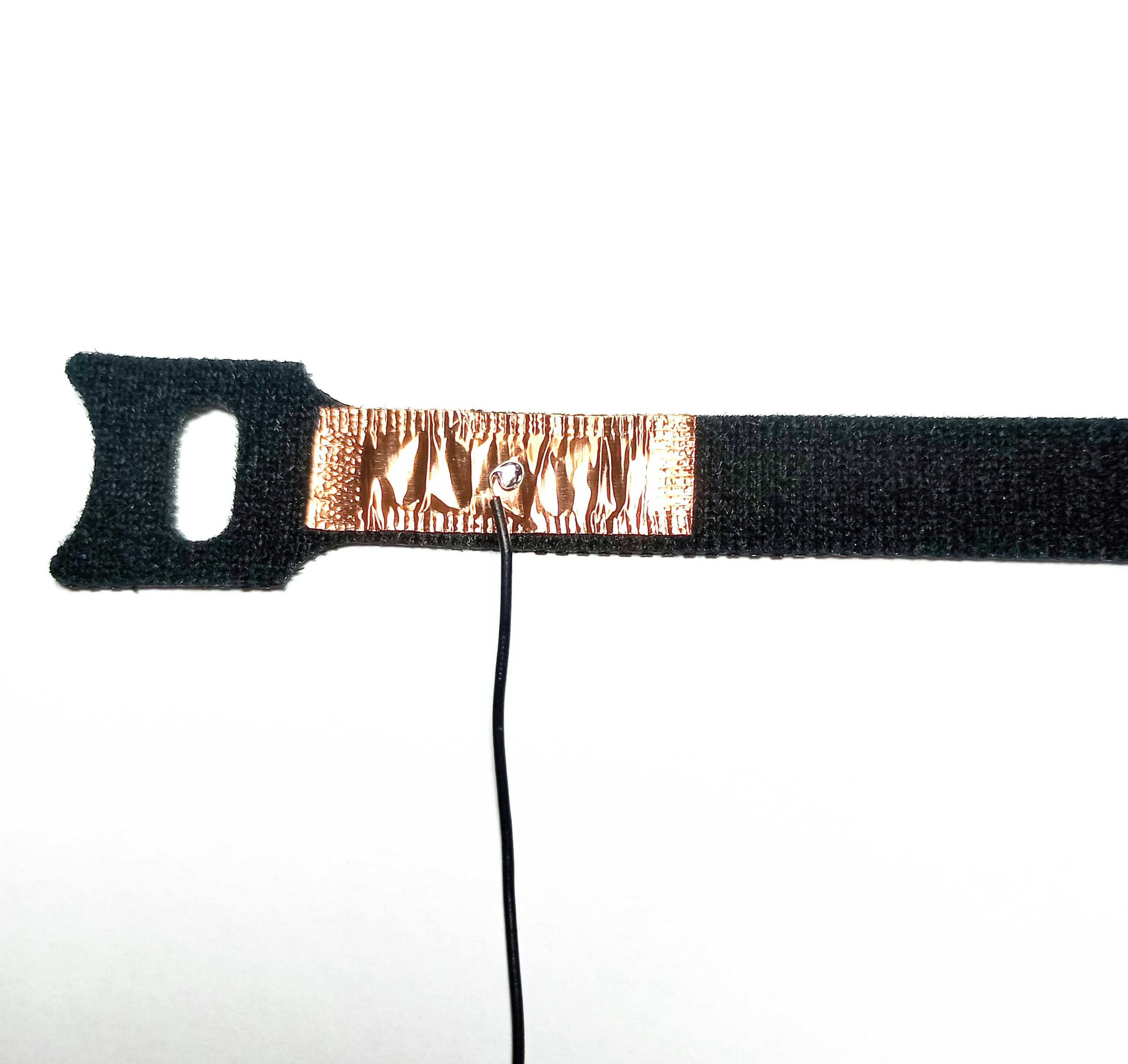
Velcro cable-organizing straps work well as the body of the sensor. Orient the Velcro strap so the soft side is facing upwards and the tail of the cable is pointing to the right. Cut four pieces of copper tape, about 3 cm in length and 1 cm in maximum width. The width of the copper tape should be just slightly less than the width of the Velcro cable. Adhere a piece of copper tape to the strap where the head meets the tail. It may help to crimp the edges of the tape to the strap with a pair of needle-nose pliers.
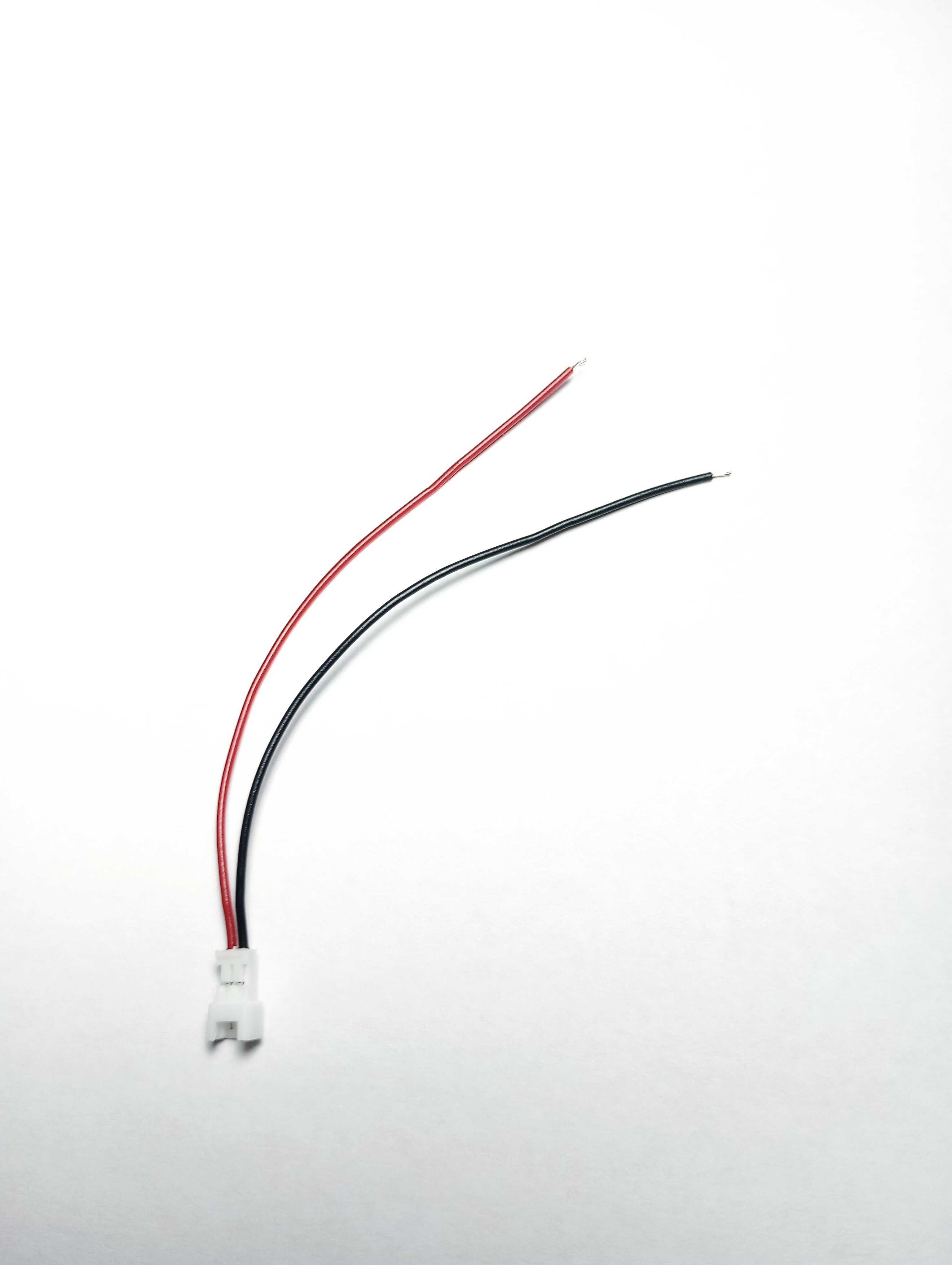
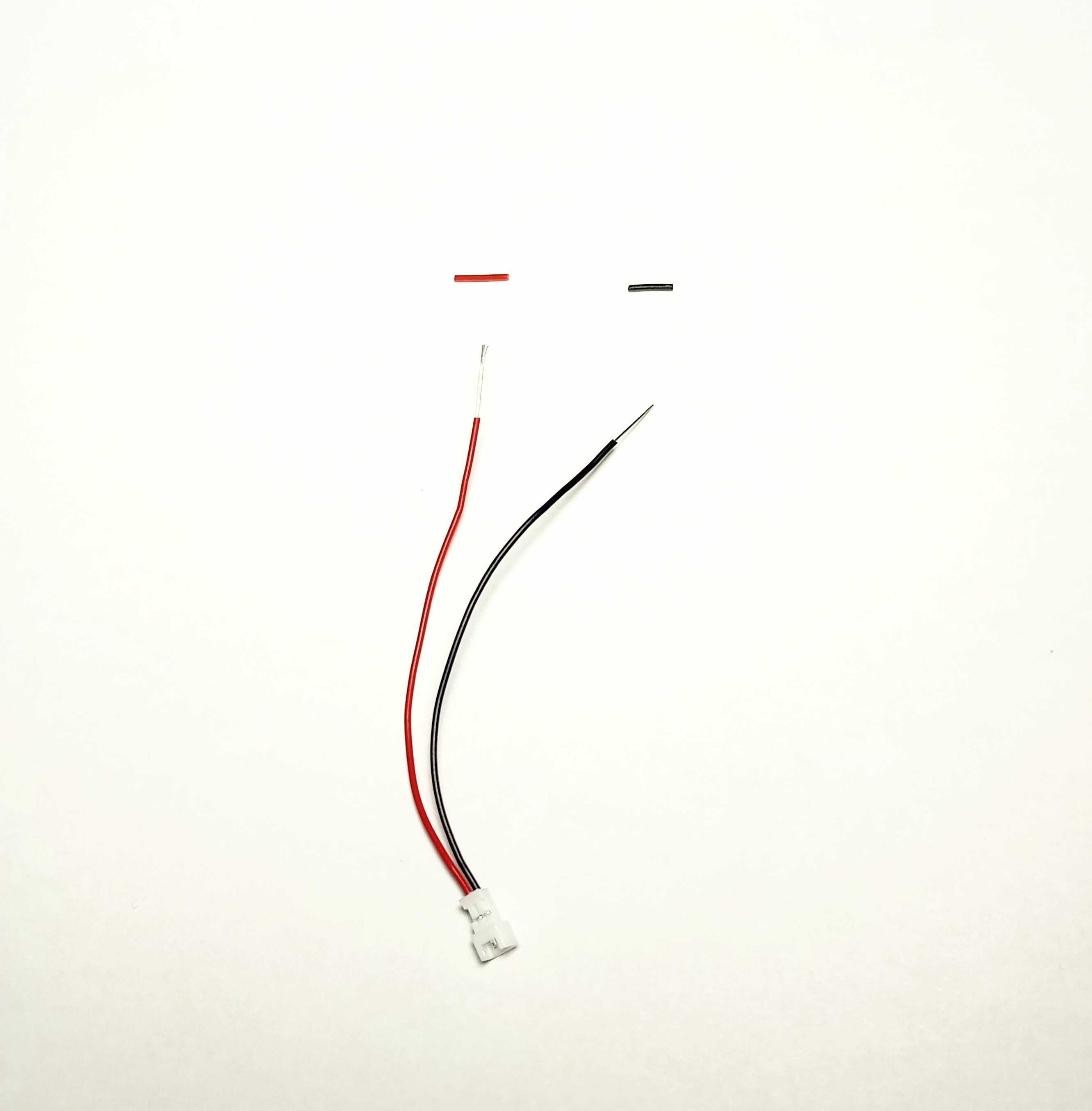
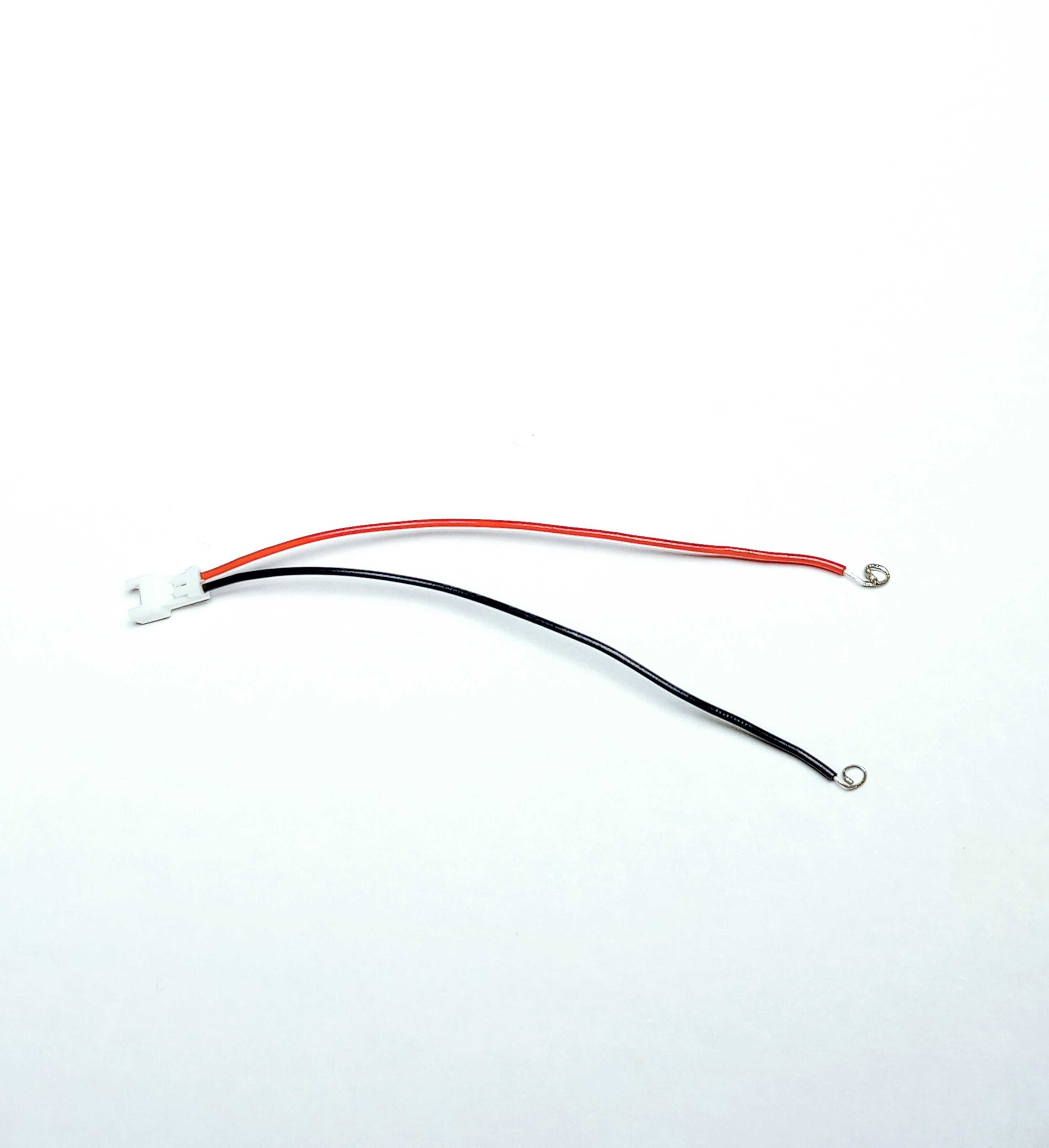
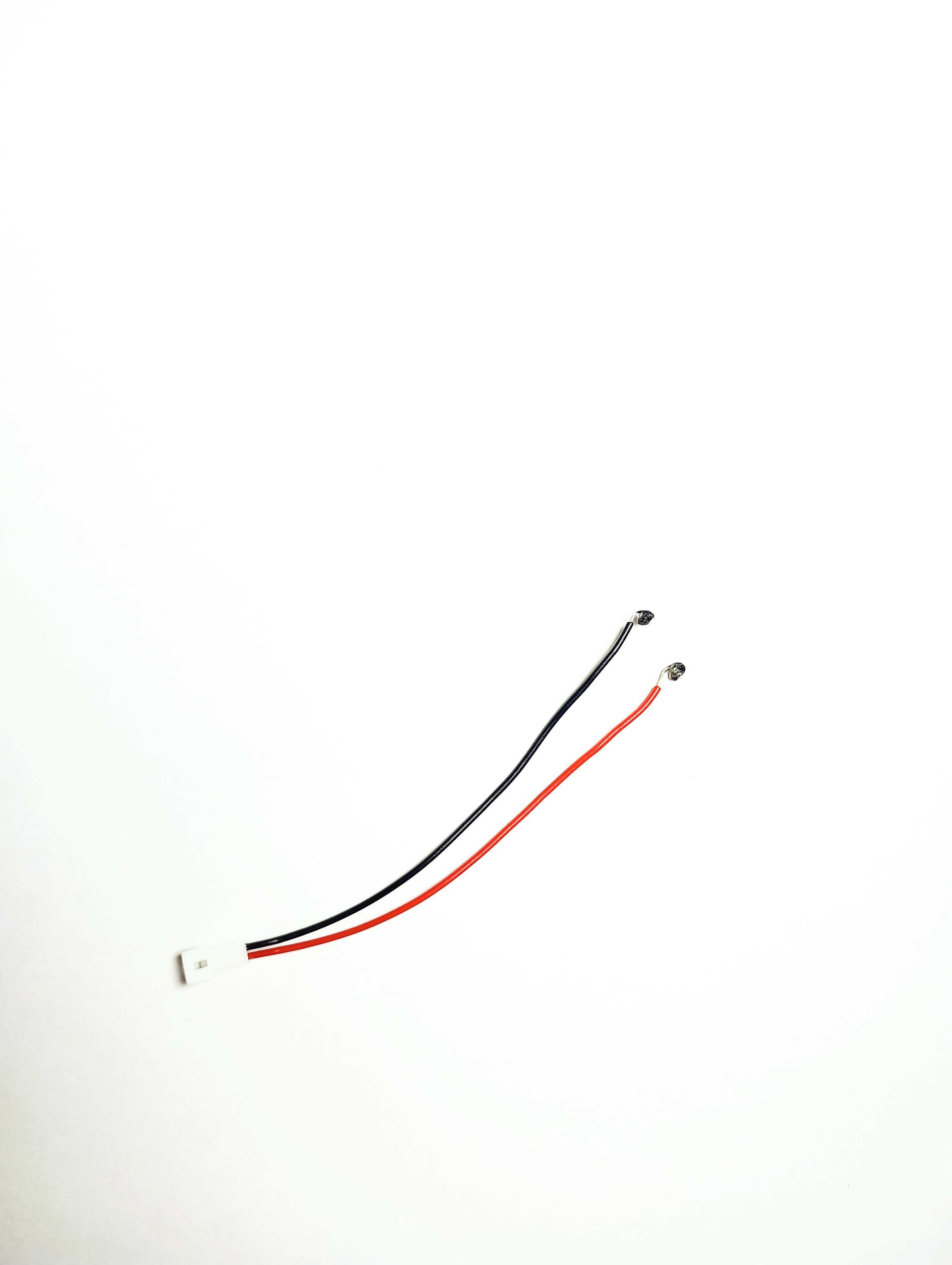
The connecting cable is what we will use to connect the sensors to the wire and ultimately the IMAGS circuit itself. This is the small square outlet with a black wire and red wire running out of it. Use a pair of wire strippers to remove about half an inch of the protective coating at the end of both wires. Carefully coat the exposed ends of the wire with solder paste, making sure to wipe off the excess. With a soldering iron heated to 300°C, lightly tap the wires to melt the solder paste into the individual wires. With the soldering iron still on, melt a very small amount of solder with the iron and spread the melted solder over the ends of the wire. This process is known as tinning the wires and will help the integrity of the wires.
Next, grab the end of the tinned wire with a pair of needle-nose pliers and twist it to make a loop at the end of each wire coming from the connector. Melt some solder to fill in the loop so the ends of the wires look like discs of solder. Then connect these wires to the copper tape on the Velcro strap. This is one of the most difficult parts, but with a bit of patience and practice it will become much easier.
Under so much heat, the Velcro straps are prone to melting and deforming. To minimize the chances of this happening, make the connection from the wire loop to the copper tape as quickly and at as low a temperature as possible. Gently tap the tip of the soldering iron to the disc of solder on the end of the connector wire while holding the wire against the copper tape. Hold for no longer than 5 seconds, remove the soldering iron, and keep the wire perfectly still. After another 5 seconds, the wire should be fully secured to the copper tape. Allow the Velcro strap 20–30 seconds to cool, then lay another piece of copper tape over the original one to hide the solder joint. Repeat the process with another Velcro strap and the other wire on the same connector. You have now created your first sensor.
Connecting wire
The IMAGS device requires a wire to connect the cable to the circuit. Because of the nature of the sensor, this wire is actually two wires twisted together. The process is simple but can be time consuming. You will need two plug connector cables, red and black 24 AWG wire, at least 4 inches of 1/16-inch heat shrink, as well as a soldering iron, solder, and solder paste. A length of 1.5 feet usually works well, but the connecting wire can be made as long or short as needed.
After cutting the two long wires, strip about half an inch of protective coating from each end. Tin the ends of the connector plugs in the same fashion as the sensors, but do not make loops. Once cool, wrap the end of the black connector plug wire around the end of the long black wire, and do the same for the red wires. Heat the soldering iron to 350 degrees and, while using a stand to hold the wires together, melt a little solder to join them. The solder used to tin the connector plug ends will also help here. Repeat this for both the black and red wire connections.
You should now have what functionally resembles the connector plug, but much longer. Cut pieces of heat shrink slightly longer than the solder joints and slide them over the connections. Hold the soldering iron just above the heat shrink so it contracts and protects each connection. After the heat shrink is in place on both sides, the wires can optionally be twisted together for neatness and compactness.