IMAGS Breadboard Instructions
Breadboad INSTRUCTIONS
To start place your arduino so that the 5V pin is on hole i1 as shown. This will make it so the board extends to row 16.
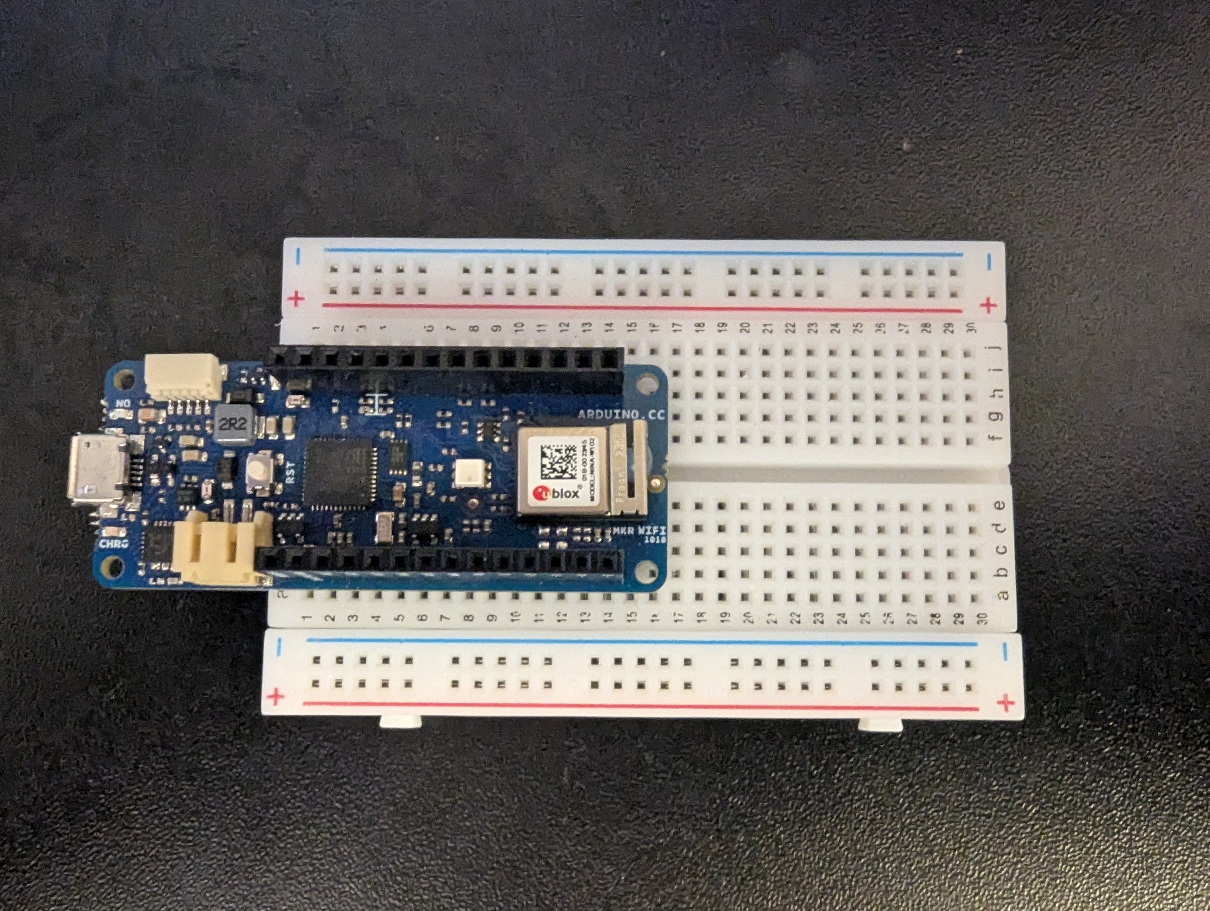 Step 1
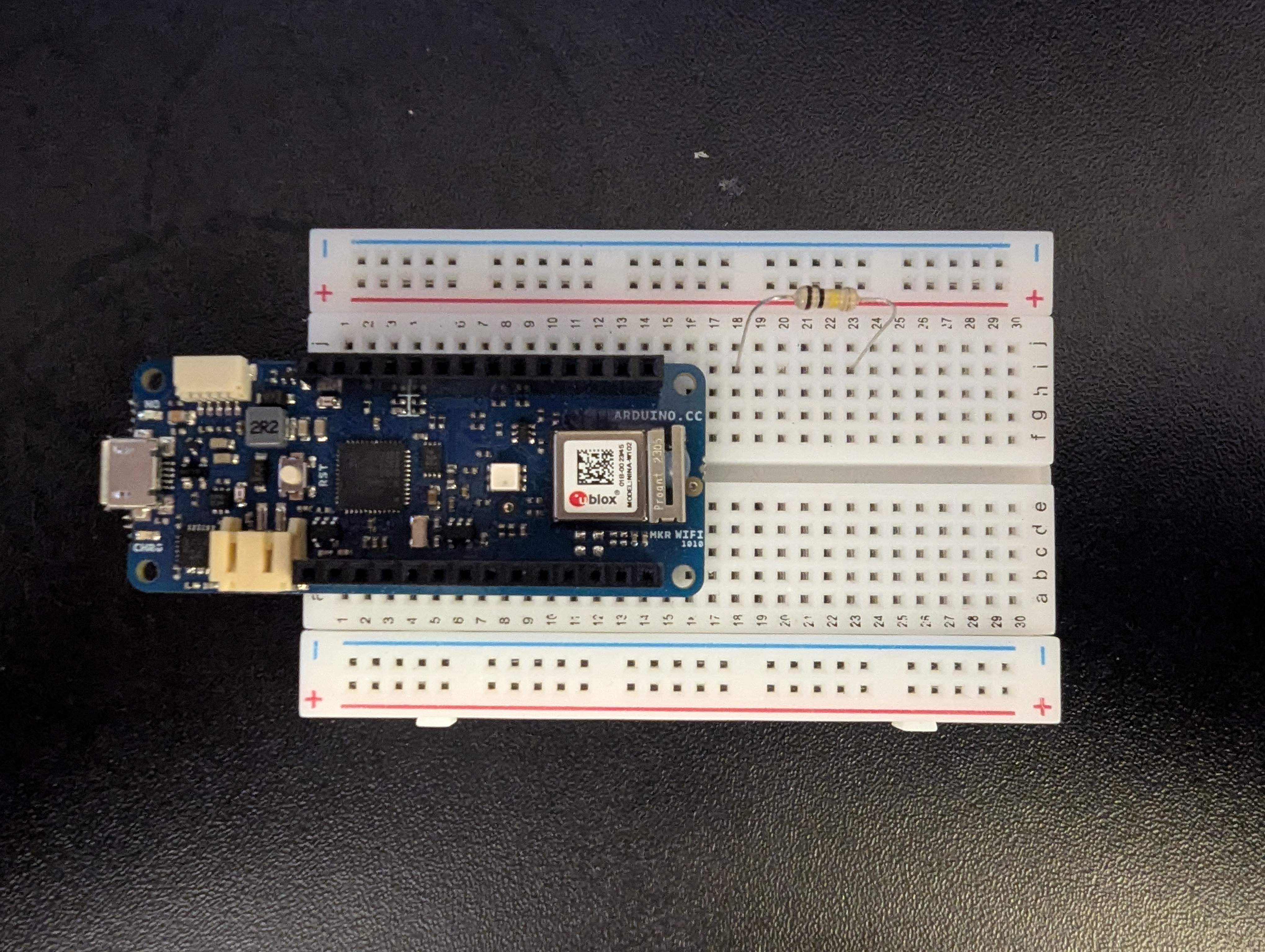 Step 2
Next take the 100k Ohm resistor and place it between pins 18 and 23 on row i.
The 68nf capacitor is then placed on the board between pins 18 and 23 on row h. This puts the capacitor in parallel with the resistor.
At this time also connect one of your short jumper wires between g18 and pin A0 on the arduino as shown in the image.
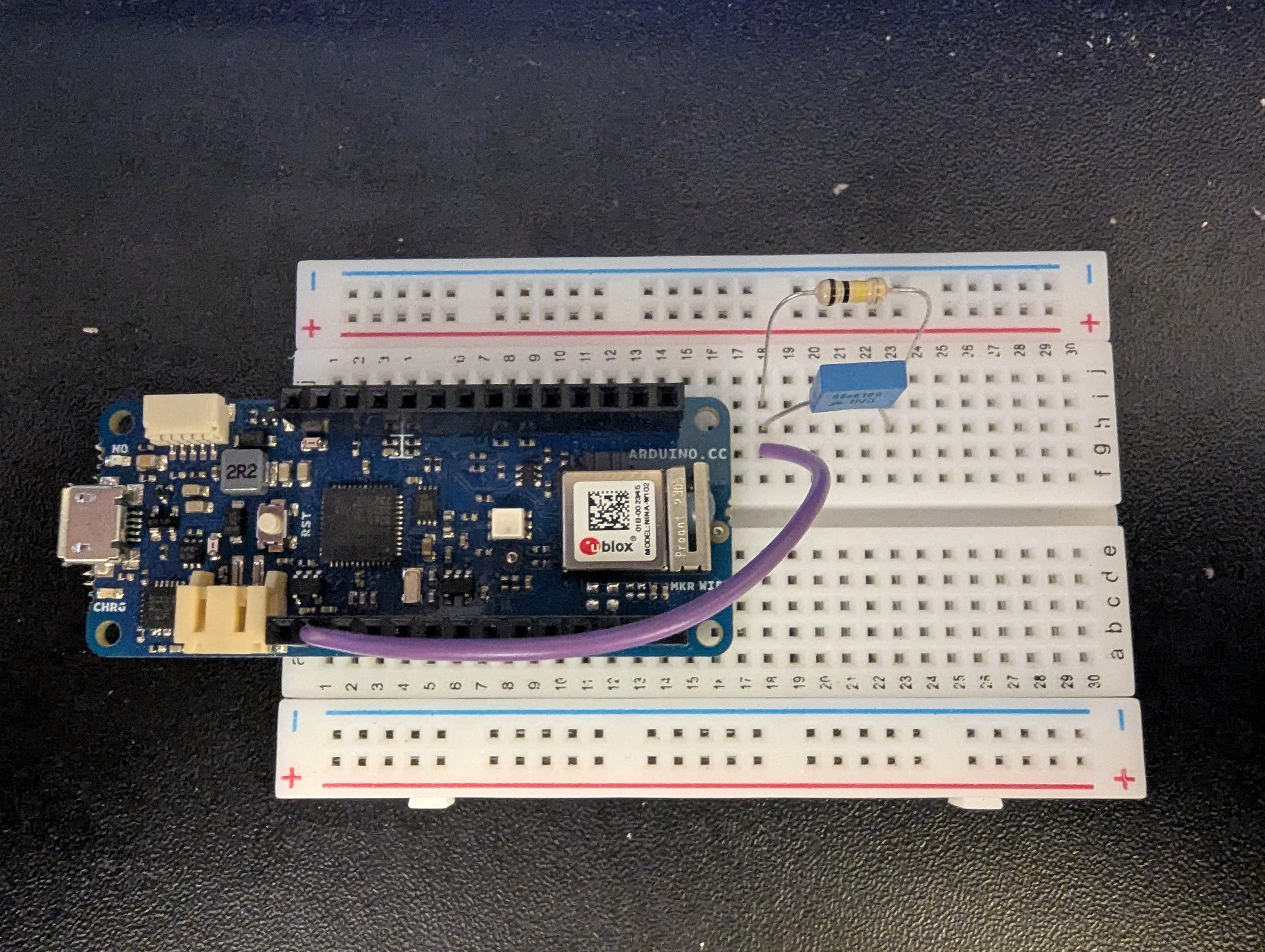 Step 3
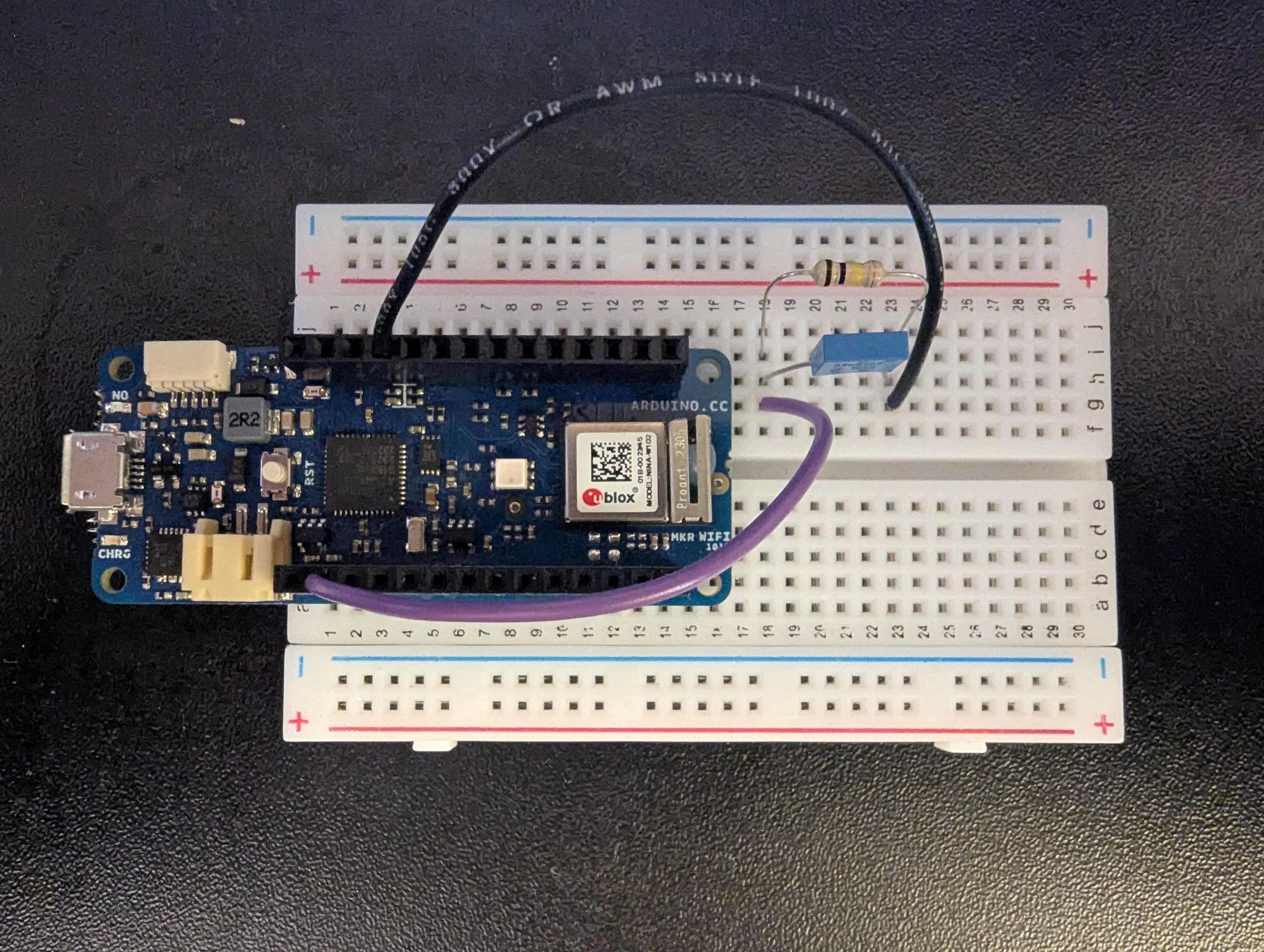 Step 4
Another short jumper wire is connected between g23 and the ground pin on the arduino as shown in the image.
The sensor will now be connected, one wire will go to the 5V pin of the arduino and another will go to i18 lining up with the resistor and capacitor.
The order of the wires does not matter and they may be interchanged.
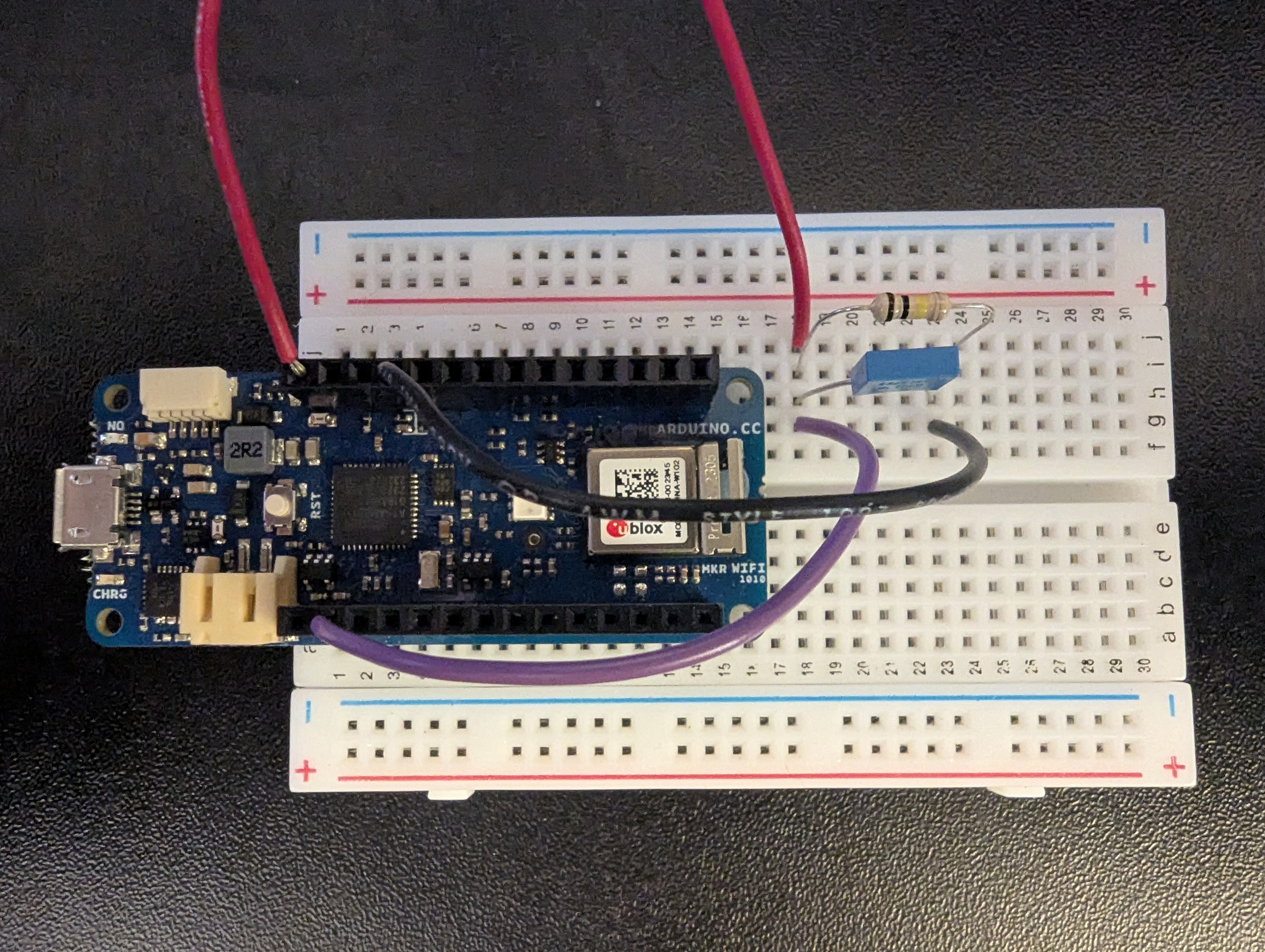 Step 5
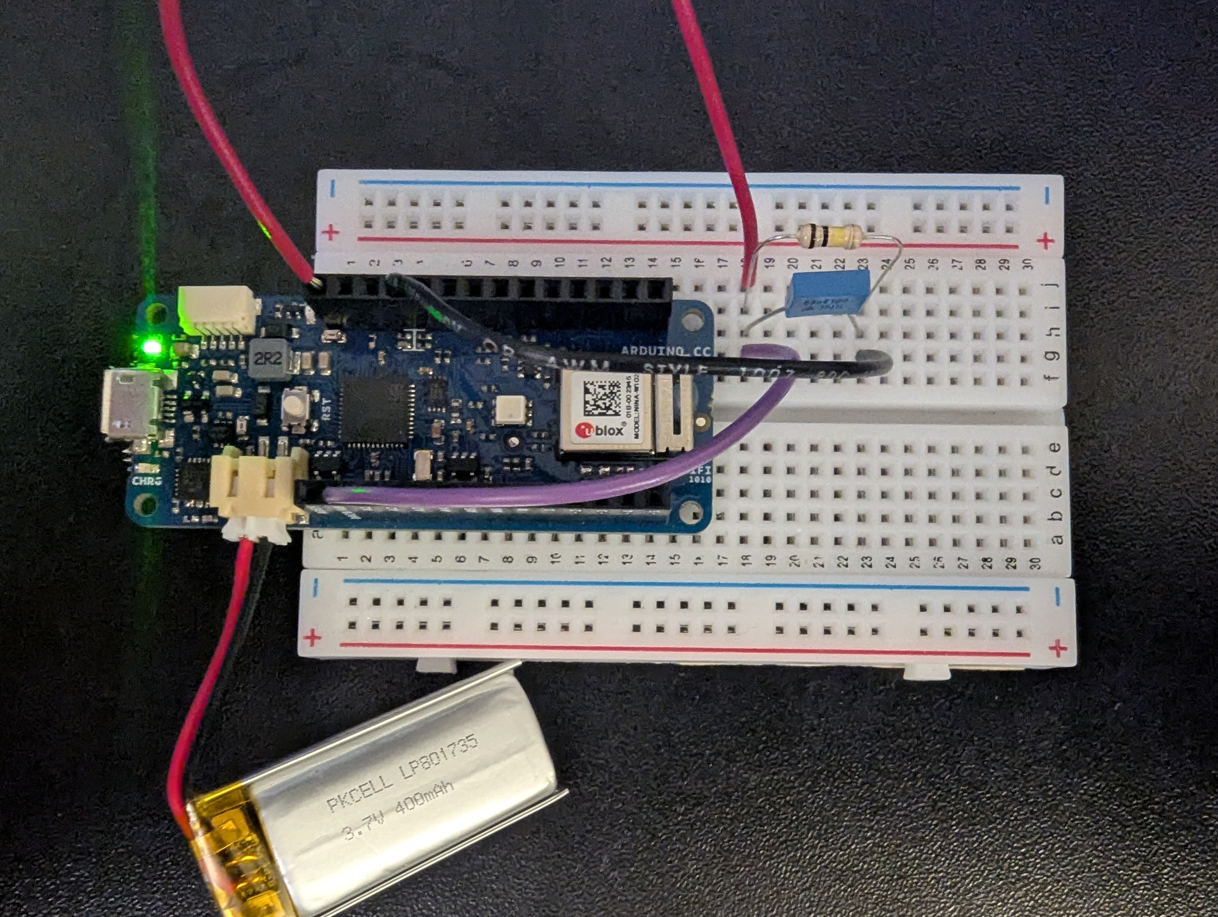 Step 6
Now the battery can be connected to the slot on the side of the arduino and it should power on and become fully functional.
At this point you should be able to connect the device with your browser and begin taking data with the sensors.
These next two steps are fully optional and serve to install an indicator LED that displays if the device is on or off.
To start with this insert a 4.7k ohm resistor between j1 and the positive rail on the breadboard.
This will make it so the entire row has power to run an LED.
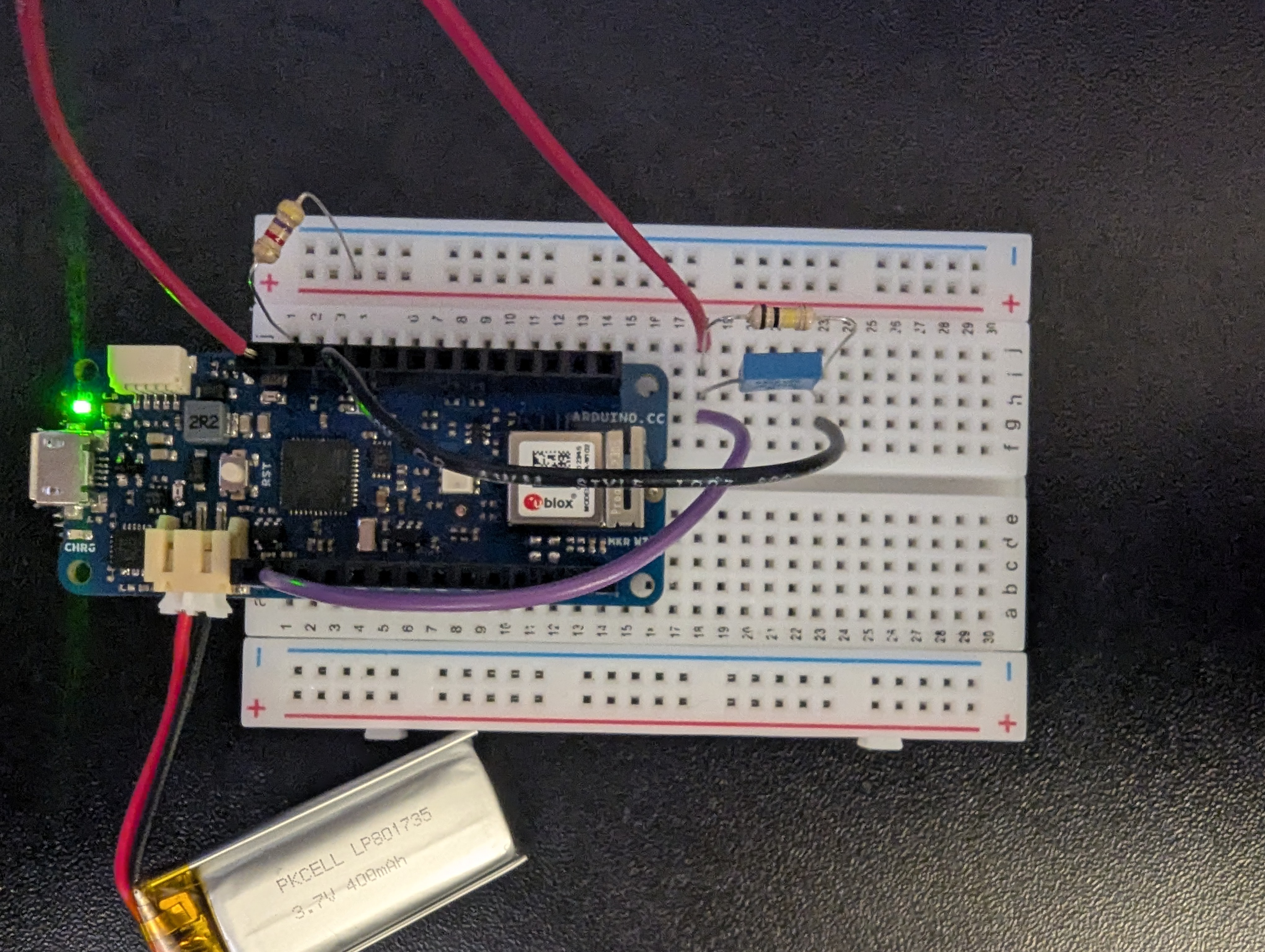 Step 7
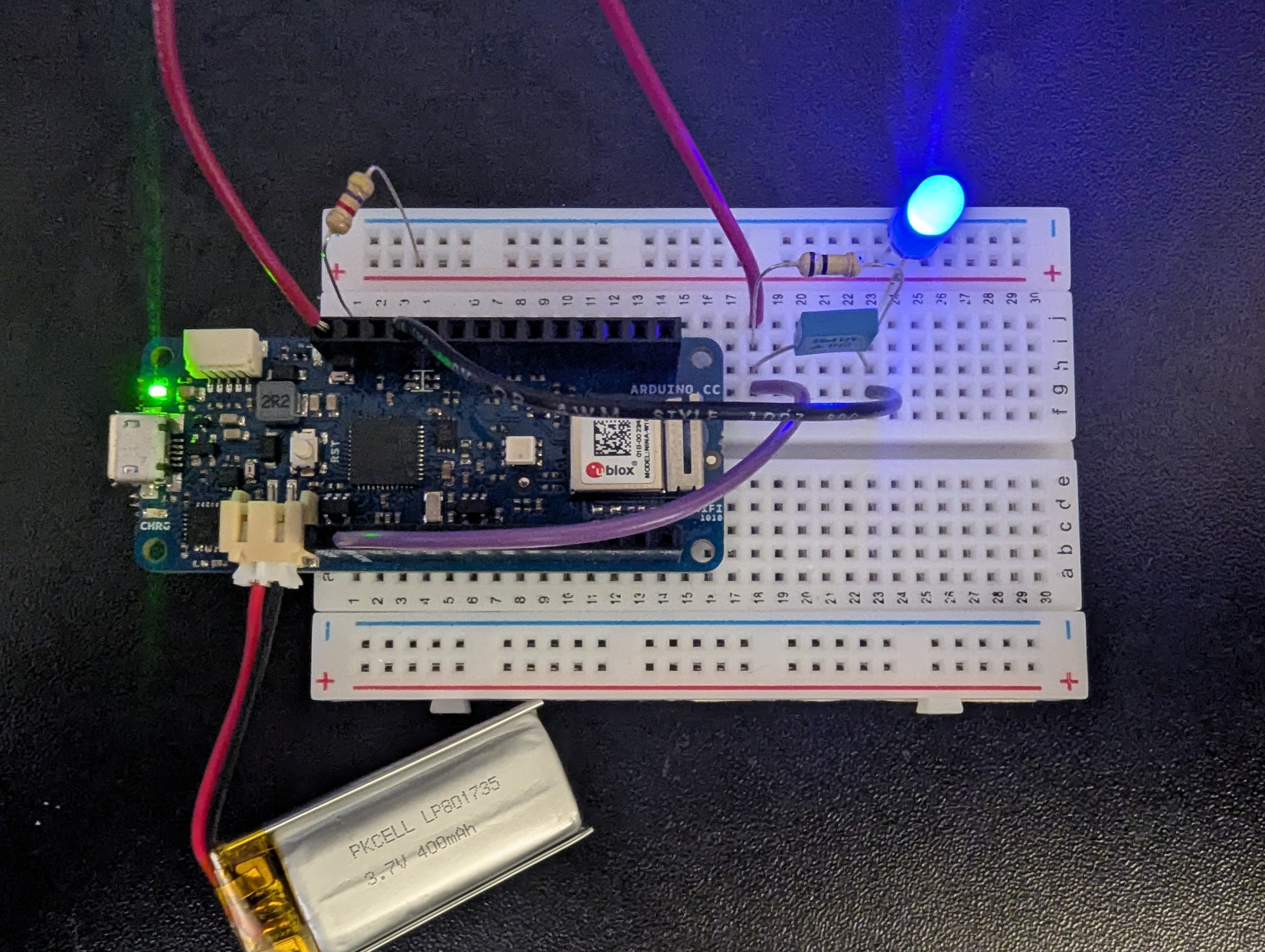 Step 8
Lastly plug the LED into both the positive rail with the longer leg of the LED, and then the shorter leg of the LED into i23.
Optionally you may also place the shorter leg of the LED somewhere else on the board to your preference and then connect it to ground with a jumper wire.
IMAGS Perfboard Instructions
To start assembly of the perfboard circuit, we first want to add the largest component, the Arduino, to the board and secure it. On a piece of 20 x 14 perfboard place the Arduino in the bottom right corner, one hole up and one hole in so that the bottom right pin of the Arduino is inserted into S-13 (double check this!)
Perfboard step 1 image placeholder
Perfboard Step 1Perfboard step 2 image placeholder
Perfboard Step 2
Using clips or tape to hold the Arduino in place, solder each pin of the Arduino into its respective hole. Remove the clips/tape and ensure that the Arduino stays in place. There should be four columns of pins next to the Arduino. This is where we will build the filter. We will use the 68nF capacitor and the 100kOhm resistor to filter the unwanted noise from our raw signal. We will place the capacitor and resistor in parallel with one side of the node connected to the sensor wire and the data pin, and the other side of the filter connected to GND.
Tin the ends of both 1.5” pieces of wire so they can easily be inserted into the perfboard holes.
Place the end of one of the wires into the A0 port of the Arduino.
This will be what reads the GSR data.
Place the other end of the A0 data wire into the perfboard hole directly before the capacitor.
Place one end of the other wire into the GND pin of the Arduino and place the other end into the perfboard connected to the capacitor/resistor node.
The ground wire will be on the opposite side of the capacitor/resistor node as the A0 wire.
Perfboard step 3 image placeholder
Perfboard Step 3Perfboard step 4 image placeholder
Perfboard Step 4
One side of the connector wire will plug into the 5V while the other will plug into the same node of the RC filter as the A0 wire.